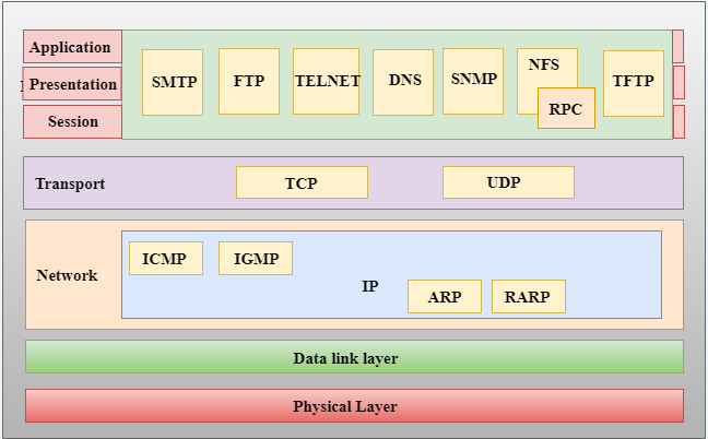
The Open Systems Interconnection model (OSI model) is a conceptual model that characterises and standardises the communication functions of a telecommunication or computing system without regard to its underlying internal structure and technology. Its goal is the interoperability of diverse communication systems with standard communication protocols. The model partitions a communication system into abstraction layers.
A layer serves the layer above it and is served by the layer below it. For example, a layer that provides error-free communications across a network provides the path needed by applications above it, while it calls the next lower layer to send and receive packets that constitute the contents of that path.
The model is a product of the Open Systems Interconnection project at the International Organization for Standardization (ISO).
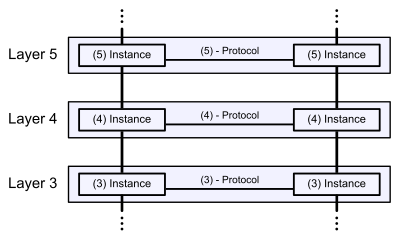
Communication in the OSI-Model (example with layers 3 to 5)
History
In the early- and mid-1970s, networking was largely either government-sponsored (NPL network in the UK, ARPANET in the US, CYCLADES in France) or vendor-developed with proprietary standards, such as IBM's Systems Network Architecture and Digital Equipment Corporation's DECnet. Public data networks were only just beginning to emerge, and these began to use the X.25 standard in the late 1970s.[1][2]
The Experimental Packet Switched System in the UK circa 1973-5 identified the need for defining higher level protocols.[1] The UK National Computing Centre publication 'Why Distributed Computing' which came from considerable research into future configurations for computer systems,[3] resulted in the UK presenting the case for an international standards committee to cover this area at the ISO meeting in Sydney in March 1977.[4]
Beginning in 1977, the International Organization for Standardization (ISO) conducted a program to develop general standards and methods of networking. A similar process evolved at the International Telegraph and Telephone Consultative Committee (CCITT, from French: Comité Consultatif International Téléphonique et Télégraphique). Both bodies developed documents that defined similar networking models. The OSI model was first defined in raw form in Washington, DC in February 1978 by Hubert Zimmermann of France and the refined but still draft standard was published by the ISO in 1980.[5]
The drafters of the reference model had to contend with many competing priorities and interests. The rate of technological change made it necessary to define standards that new systems could converge to rather than standardizing procedures after the fact; the reverse of the traditional approach to developing standards.[6] Although not a standard itself, it was a framework in which future standards could be defined.[7]
In 1983, the CCITT and ISO documents were merged to form The Basic Reference Model for Open Systems Interconnection, usually referred to as the Open Systems Interconnection Reference Model, OSI Reference Model, or simply OSI model. It was published in 1984 by both the ISO, as standard ISO 7498, and the renamed CCITT (now called the Telecommunications Standardization Sector of the International Telecommunication Union or ITU-T) as standard X.200.
OSI had two major components, an abstract model of networking, called the Basic Reference Model or seven-layer model, and a set of specific protocols. The OSI reference model was a major advance in the teaching of network concepts. It promoted the idea of a consistent model of protocol layers, defining interoperability between network devices and software.
The concept of a seven-layer model was provided by the work of Charles Bachman at Honeywell Information Systems.[8] Various aspects of OSI design evolved from experiences with the NPL network, ARPANET, CYCLADES, EIN, and the International Networking Working Group (IFIP WG6.1). In this model, a networking system was divided into layers. Within each layer, one or more entities implement its functionality. Each entity interacted directly only with the layer immediately beneath it and provided facilities for use by the layer above it.
The OSI standards documents are available from the ITU-T as the X.200-series of recommendations.[9] Some of the protocol specifications were also available as part of the ITU-T X series. The equivalent ISO and ISO/IEC standards for the OSI model were available from ISO. Not all are free of charge.[10]
OSI was an industry effort, attempting to get industry participants to agree on common network standards to provide multi-vendor interoperability.[11] It was common for large networks to support multiple network protocol suites, with many devices unable to interoperate with other devices because of a lack of common protocols. For a period in the late 1980s and early 1990s, engineers, organizations and nations became polarized over the issue of which standard, the OSI model or the Internet protocol suite, would result in the best and most robust computer networks.[4][12][13] However, while OSI developed its networking standards in the late 1980s,[14][15] TCP/IP came into widespread use on multi-vendor networks for internetworking.
The OSI model is still used as a reference for teaching and documentation;[16] however, the OSI protocols originally conceived for the model did not gain popularity. Some engineers argue the OSI reference model is still relevant to cloud computing.[17] Others say the original OSI model doesn't fit today's networking protocols and have suggested instead a simplified approach.[18]
Definitions
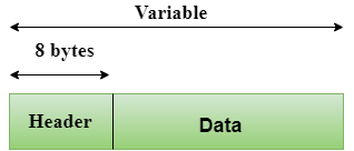
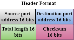
At each level N, two entities at the communicating devices (layer N peers) exchange protocol data units (PDUs) by means of a layer N protocol. Each PDU contains a payload, called the service data unit (SDU), along with protocol-related headers or footers.Communication protocols enable an entity in one host to interact with a corresponding entity at the same layer in another host. Service definitions, like the OSI Model, abstractly describe the functionality provided to an (N)-layer by an (N-1) layer, where N is one of the seven layers of protocols operating in the local host.
Data processing by two communicating OSI-compatible devices proceeds as follows:
- The data to be transmitted is composed at the topmost layer of the transmitting device (layer N) into a protocol data unit (PDU).
- The PDU is passed to layer N-1, where it is known as the service data unit (SDU).
- At layer N-1 the SDU is concatenated with a header, a footer, or both, producing a layer N-1 PDU. It is then passed to layer N-2.
- The process continues until reaching the lowermost level, from which the data is transmitted to the receiving device.
- At the receiving device the data is passed from the lowest to the highest layer as a series of SDUs while being successively stripped from each layer's header or footer until reaching the topmost layer, where the last of the data is consumed.
Standards documents[edit]
The OSI model was defined in ISO/IEC 7498 which consists of the following parts:
- ISO/IEC 7498-1 The Basic Model
- ISO/IEC 7498-2 Security Architecture
- ISO/IEC 7498-3 Naming and addressing
- ISO/IEC 7498-4 Management framework
ISO/IEC 7498-1 is also published as ITU-T Recommendation X.200.
Layer architecture[edit]
The recommendation X.200 describes seven layers, labelled 1 to 7. Layer 1 is the lowest layer in this model.
OSI model| Layer | Protocol data unit (PDU) | Function[19] |
|---|
Host
layers | 7 | Application | Data | High-level APIs, including resource sharing, remote file access |
|---|
| 6 | Presentation | Translation of data between a networking service and an application; including character encoding, data compression and encryption/decryption |
| 5 | Session | Managing communication sessions, i.e., continuous exchange of information in the form of multiple back-and-forth transmissions between two nodes |
| 4 | Transport | Segment, Datagram | Reliable transmission of data segments between points on a network, including segmentation, acknowledgement and multiplexing |
Media
layers | 3 | Network | Packet | Structuring and managing a multi-node network, including addressing, routing and traffic control |
|---|
| 2 | Data link | Frame | Reliable transmission of data frames between two nodes connected by a physical layer |
| 1 | Physical | Bit, Symbol | Transmission and reception of raw bit streams over a physical medium |
Layer 1: Physical Layer[edit]
The physical layer is responsible for the transmission and reception of unstructured raw data between a device and a physical transmission medium. It converts the digital bits into electrical, radio, or optical signals. Layer specifications define characteristics such as voltage levels, the timing of voltage changes, physical data rates, maximum transmission distances, modulation scheme, channel access method and physical connectors. This includes the layout of pins, voltages, line impedance, cable specifications, signal timing and frequency for wireless devices. Bit rate control is done at the physical layer and may define transmission mode as simplex, half duplex, and full duplex. The components of a physical layer can be described in terms of a network topology. Physical layer specifications are included in the specifications for the ubiquitous Bluetooth, Ethernet, and USB standards. An example of a less well-known physical layer specification would be for the CAN standard.
Layer 2: Data Link Layer[edit]
The data link layer provides node-to-node data transfer—a link between two directly connected nodes. It detects and possibly corrects errors that may occur in the physical layer. It defines the protocol to establish and terminate a connection between two physically connected devices. It also defines the protocol for flow control between them.
IEEE 802 divides the data link layer into two sublayers:[20]
- Medium access control (MAC) layer – responsible for controlling how devices in a network gain access to a medium and permission to transmit data.
- Logical link control (LLC) layer – responsible for identifying and encapsulating network layer protocols, and controls error checking and frame synchronization.
The MAC and LLC layers of IEEE 802 networks such as 802.3 Ethernet, 802.11 Wi-Fi, and 802.15.4 ZigBee operate at the data link layer.
The Point-to-Point Protocol (PPP) is a data link layer protocol that can operate over several different physical layers, such as synchronous and asynchronous serial lines.
The ITU-T G.hn standard, which provides high-speed local area networking over existing wires (power lines, phone lines and coaxial cables), includes a complete data link layer that provides both error correction and flow control by means of a selective-repeat sliding-window protocol.
Security, specifically (authenticated) encryption, at this layer can be applied with MACSec.
Layer 3: Network Layer[edit]
The network layer provides the functional and procedural means of transferring variable length data sequences (called packets) from one node to another connected in "different networks". A network is a medium to which many nodes can be connected, on which every node has an address and which permits nodes connected to it to transfer messages to other nodes connected to it by merely providing the content of a message and the address of the destination node and letting the network find the way to deliver the message to the destination node, possibly routing it through intermediate nodes. If the message is too large to be transmitted from one node to another on the data link layer between those nodes, the network may implement message delivery by splitting the message into several fragments at one node, sending the fragments independently, and reassembling the fragments at another node. It may, but does not need to, report delivery errors.
Message delivery at the network layer is not necessarily guaranteed to be reliable; a network layer protocol may provide reliable message delivery, but it need not do so.
A number of layer-management protocols, a function defined in the management annex, ISO 7498/4, belong to the network layer. These include routing protocols, multicast group management, network-layer information and error, and network-layer address assignment. It is the function of the payload that makes these belong to the network layer, not the protocol that carries them.[21]
Layer 4: Transport Layer[edit]
The transport layer provides the functional and procedural means of transferring variable-length data sequences from a source to a destination host, while maintaining the quality of service functions.
The transport layer controls the reliability of a given link through flow control, segmentation/desegmentation, and error control. Some protocols are state- and connection-oriented. This means that the transport layer can keep track of the segments and retransmit those that fail delivery. The transport layer also provides the acknowledgement of the successful data transmission and sends the next data if no errors occurred. The transport layer creates segments out of the message received from the application layer. Segmentation is the process of dividing a long message into smaller messages.
OSI defines five classes of connection-mode transport protocols ranging from class 0 (which is also known as TP0 and provides the fewest features) to class 4 (TP4, designed for less reliable networks, similar to the Internet). Class 0 contains no error recovery and was designed for use on network layers that provide error-free connections. Class 4 is closest to TCP, although TCP contains functions, such as the graceful close, which OSI assigns to the session layer. Also, all OSI TP connection-mode protocol classes provide expedited data and preservation of record boundaries. Detailed characteristics of TP0-4 classes are shown in the following table:[22]
| Feature name | TP0 | TP1 | TP2 | TP3 | TP4 |
|---|
| Connection-oriented network | Yes | Yes | Yes | Yes | Yes |
| Connectionless network | No | No | No | No | Yes |
| Concatenation and separation | No | Yes | Yes | Yes | Yes |
| Segmentation and reassembly | Yes | Yes | Yes | Yes | Yes |
| Error recovery | No | Yes | Yes | Yes | Yes |
| Reinitiate connectiona | No | Yes | No | Yes | No |
| Multiplexing / demultiplexing over single virtual circuit | No | No | Yes | Yes | Yes |
| Explicit flow control | No | No | Yes | Yes | Yes |
| Retransmission on timeout | No | No | No | No | Yes |
| Reliable transport service | No | Yes | No | Yes | Yes |
| a If an excessive number of PDUs are unacknowledged. |
An easy way to visualize the transport layer is to compare it with a post office, which deals with the dispatch and classification of mail and parcels sent. A post office inspects only the outer envelope of mail to determine its delivery. Higher layers may have the equivalent of double envelopes, such as cryptographic presentation services that can be read by the addressee only. Roughly speaking, tunnelling protocols operate at the transport layer, such as carrying non-IP protocols such as IBM's SNA or Novell's IPX over an IP network, or end-to-end encryption with IPsec. While Generic Routing Encapsulation (GRE) might seem to be a network-layer protocol, if the encapsulation of the payload takes place only at the endpoint, GRE becomes closer to a transport protocol that uses IP headers but contains complete Layer 2 frames or Layer 3 packets to deliver to the endpoint. L2TP carries PPP frames inside transport segments.
Although not developed under the OSI Reference Model and not strictly conforming to the OSI definition of the transport layer, the Transmission Control Protocol (TCP) and the User Datagram Protocol (UDP) of the Internet Protocol Suite are commonly categorized as layer-4 protocols within OSI.
Transport Layer Security (TLS) provide security at this layer.
Layer 5: Session Layer
The session layer controls the dialogues (connections) between computers. It establishes, manages and terminates the connections between the local and remote application. It provides for full-duplex, half-duplex, or simplex operation, and establishes procedures for checkpointing, suspending, restarting, and terminating a session. In the OSI model, this layer is responsible for gracefully closing a session, which is handled in the Transmission Control Protocol at the transport layer in the Internet Protocol Suite. This layer is also responsible for session checkpointing and recovery, which is not usually used in the Internet Protocol Suite. The session layer is commonly implemented explicitly in application environments that use remote procedure calls.
Layer 6: Presentation Layer[edit]
The presentation layer establishes context between application-layer entities, in which the application-layer entities may use different syntax and semantics if the presentation service provides a mapping between them. If a mapping is available, presentation protocol data units are encapsulated into session protocol data units and passed down the protocol stack.
This layer provides independence from data representation by translating between application and network formats. The presentation layer transforms data into the form that the application accepts. This layer formats data to be sent across a network. It is sometimes called the syntax layer.[23] The presentation layer can include compression functions.[24] The Presentation Layer negotiates the Transfer Syntax.
The original presentation structure used the Basic Encoding Rules of Abstract Syntax Notation One (ASN.1), with capabilities such as converting an EBCDIC-coded text file to an ASCII-coded file, or serialization of objects and other data structures from and to XML. ASN.1 effectively makes an application protocol invariant with respect to syntax.
Layer 7: Application Layer[edit]
The application layer is the OSI layer closest to the end user, which means both the OSI application layer and the user interact directly with the software application. This layer interacts with software applications that implement a communicating component. Such application programs fall outside the scope of the OSI model. Application-layer functions typically include identifying communication partners, determining resource availability, and synchronizing communication. When identifying communication partners, the application layer determines the identity and availability of communication partners for an application with data to transmit. The most important distinction in the application layer is the distinction between the application-entity and the application. For example, a reservation website might have two application-entities: one using HTTP to communicate with its users, and one for a remote database protocol to record reservations. Neither of these protocols have anything to do with reservations. That logic is in the application itself. The application layer has no means to determine the availability of resources in the network.
Cross-layer functions[edit]
Cross-layer functions are services that are not tied to a given layer, but may affect more than one layer.[25] Some orthogonal aspects, such as management and security, involve all of the layers (See ITU-T X.800 Recommendation[26]). These services are aimed at improving the CIA triad—confidentiality, integrity, and availability—of the transmitted data. Cross-layer functions are the norm, in practice, because the availability of a communication service is determined by the interaction between network design and network management protocols.
Specific examples of cross-layer functions include the following:
- Security service (telecommunication)[26] as defined by ITU-T X.800 recommendation.
- Management functions, i.e. functions that permit to configure, instantiate, monitor, terminate the communications of two or more entities: there is a specific application-layer protocol, common management information protocol (CMIP) and its corresponding service, common management information service (CMIS), they need to interact with every layer in order to deal with their instances.
- Multiprotocol Label Switching (MPLS), ATM, and X.25 are 3a protocols. OSI subdivides the Network Layer into three sublayers: 3a) Subnetwork Access, 3b) Subnetwork Dependent Convergence and 3c) Subnetwork Independent Convergence.[27] It was designed to provide a unified data-carrying service for both circuit-based clients and packet-switching clients which provide a datagram-based service model. It can be used to carry many different kinds of traffic, including IP packets, as well as native ATM, SONET, and Ethernet frames. Sometimes one sees reference to a Layer 2.5.
- Cross MAC and PHY Scheduling is essential in wireless networks because of the time-varying nature of wireless channels. By scheduling packet transmission only in favourable channel conditions, which requires the MAC layer to obtain channel state information from the PHY layer, network throughput can be significantly improved and energy waste can be avoided.[28]
Programming interfaces[edit]
Neither the OSI Reference Model, nor any OSI protocol specifications, outline any programming interfaces, other than deliberately abstract service descriptions. Protocol specifications define a methodology for communication between peers, but the software interfaces are implementation-specific.
For example, the Network Driver Interface Specification (NDIS) and Open Data-Link Interface (ODI) are interfaces between the media (layer 2) and the network protocol (layer 3).
Comparison to other networking suites[edit]
Comparison with TCP/IP model[edit]
The design of protocols in the TCP/IP model of the Internet does not concern itself with strict hierarchical encapsulation and layering.[34] RFC 3439 contains a section entitled "Layering considered harmful".[35] TCP/IP does recognize four broad layers of functionality which are derived from the operating scope of their contained protocols: the scope of the software application; the host-to-host transport path; the internetworking range; and the scope of the direct links to other nodes on the local network.[36]
Despite using a different concept for layering than the OSI model, these layers are often compared with the OSI layering scheme in the following manner:
- The Internet application layer maps to the OSI application layer, presentation layer, and most of the session layer.
- The TCP/IP transport layer maps to the graceful close function of the OSI session layer as well as the OSI transport layer.
- The internet layer performs functions as those in a subset of the OSI network layer.
- The link layer corresponds to the OSI data link layer and may include similar functions as the physical layer, as well as some protocols of the OSI's network layer.
These comparisons are based on the original seven-layer protocol model as defined in ISO 7498, rather than refinements in the internal organization of the network layer.
The OSI protocol suite that was specified as part of the OSI project was considered by many as too complicated and inefficient, and to a large extent unimplementable.[37] Taking the "forklift upgrade" approach to networking, it specified eliminating all existing networking protocols and replacing them at all layers of the stack. This made implementation difficult and was resisted by many vendors and users with significant investments in other network technologies. In addition, the protocols included so many optional features that many vendors' implementations were not interoperable.[37]
Although the OSI model is often still referenced, the Internet protocol suite has become the standard for networking. TCP/IP's pragmatic approach to computer networking and to independent implementations of simplified protocols made it a practical methodology.[37] Some protocols and specifications in the OSI stack remain in use, one example being IS-IS, which was specified for OSI as ISO/IEC 10589:2002 and adapted for Internet use with TCP/IP as RFC 1142.